
Description
While flying in severe convective weather, aircrafts are easy to be affected by lightning strikes, which may cause high temperature, high voltage and high magnetic field, leading to fire break, corrosion, explosion, deformation and strength reduction etc. LVG 3000 is 3ctest’s self-developed testing system, which can simulate the environment where an aircraft flies and find the attachment points that is easy to be struck by lightning, fully in compliance with the test requirement specified in MIL-STD-464C, DO 160 section23, SAE ARP5416, GJB 1389A and GJB 3567 etc. It can also be used for tests on the whole aircraft, aerospace materials, ships, missiles, military vehicles, radars etc.
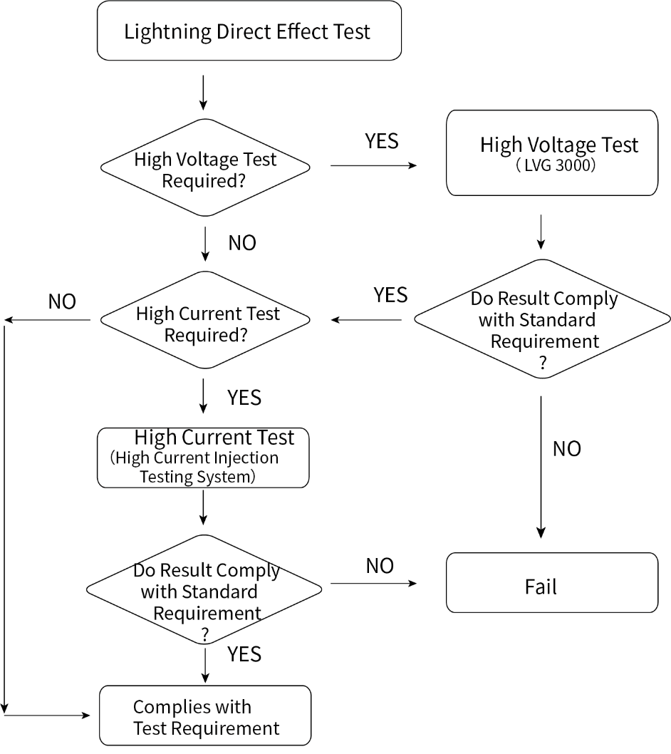
Flow Chart for Lightning Direct Effect Test:
Waveforms:
According to MIL-STD-464C and SAE ARP5412, there are 4 waveforms to be tested as below.
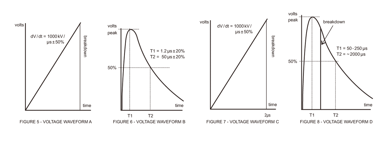
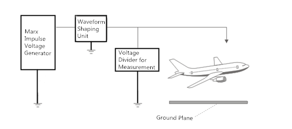
Diagram for HV Strike Attachment Point Test:
Waveform shaping unit includes adjusting unit of lightning waves, steep waves or operating waves.
Waveform Explanation:
Voltage waveform A: This waveform rises at a rate of 1000 kV/µs (±50%) until its increase is interrupted by voltage breakdown of the intervening air gap, resulting in the puncture of, or flashover across, the object under test. At that time the voltage collapses to zero. The rate of voltage collapse or the decay time of the voltage if breakdown does not occur (open circuit voltage of a lightning voltage generator) is not specified.
Voltage waveform D is a voltage rising to peak in between 50 μs and 250 μs with a time to 50% of peak of approximately 2000 μs.
Voltage waveform B: This waveform is a 1.2 µs x 50 µs waveform which is the electrical industry standard for impulse dielectric tests.
Voltage waveform C: This is a chopped voltage waveform in which breakdown of the gap between an object under test and the test electrodes occurs at 2 µs (±50%). The amplitude of the voltage at time of breakdown and the rate-of-rise of voltage prior to breakdown are not specified.
Voltage waveform D: The slow fronted Voltage Waveform D has a rise time between 50 and 250 µs so as to allow time for streamers from an object to develop. It should give a higher strike rate to the low probability regions than otherwise might have been expected.

Reviews
There are no reviews yet.