Indirect Lightning Induced Transient

Model:LSS 160SM6 & LIS 100B

The LSS 160SM6 and LIS 100B test systems are designed according to RTCA/DO-160 Section 22, The LSS 160SM6 is capable of generating waveforms 1,4 and 5A/5B, and LIS 100B is of waveforms 2, 3 and 6.

In Stock
Enquire Now

Description

When an aircraft is flying in severe convection environment, it will be frequently affected by lightning stroke, which will generate transient induced voltage or current on circuits and cables of airborne equipment, such phenomenon is called indirect lightning effect. It may make the aircraft get out of control, even bring about fuselage fire and other serious accidents. For safety reasons, the airborne equipment must be designed properly and tested completely to ensure the system and equipment with critical safety function to perform normally and its flight security when the aircraft is influenced by lightning stroke.
The LSS 160SM6 and LIS 100B test systems are designed according to RTCA/DO-160 Section 22, The LSS 160SM6 is capable of generating waveforms 1,4 and 5A/5B, and LIS 100B is of waveforms 2, 3 and 6. Both test level are from 1 to 3 for pins injection test and cable bundle test; Additionally, the test system is not only meet the test requirement of lightning induced transients conducted susceptibility in MIL-STD-461G CS117.
The test system includes various test auxiliary equipment to make it convenient to conduct tests, such as coupling transformer, power blocking device, transient blocking device, pin injection probe, external DC capacitor etc. What’s more, the Corelab software is also available for remote control test, which makes your test easy and convenient.

Features:

  • Modular design, the waveform module is detachable;
  • Capable of generating 6 kinds of waveforms and performing pins injection test and cable bundle test;
  • 5.7 inch color touch screen with easy and distinct operation control;
  • Phase synchronization function in signal pins & power pins-direct injection method;
  • Corelab software is available for remote control.

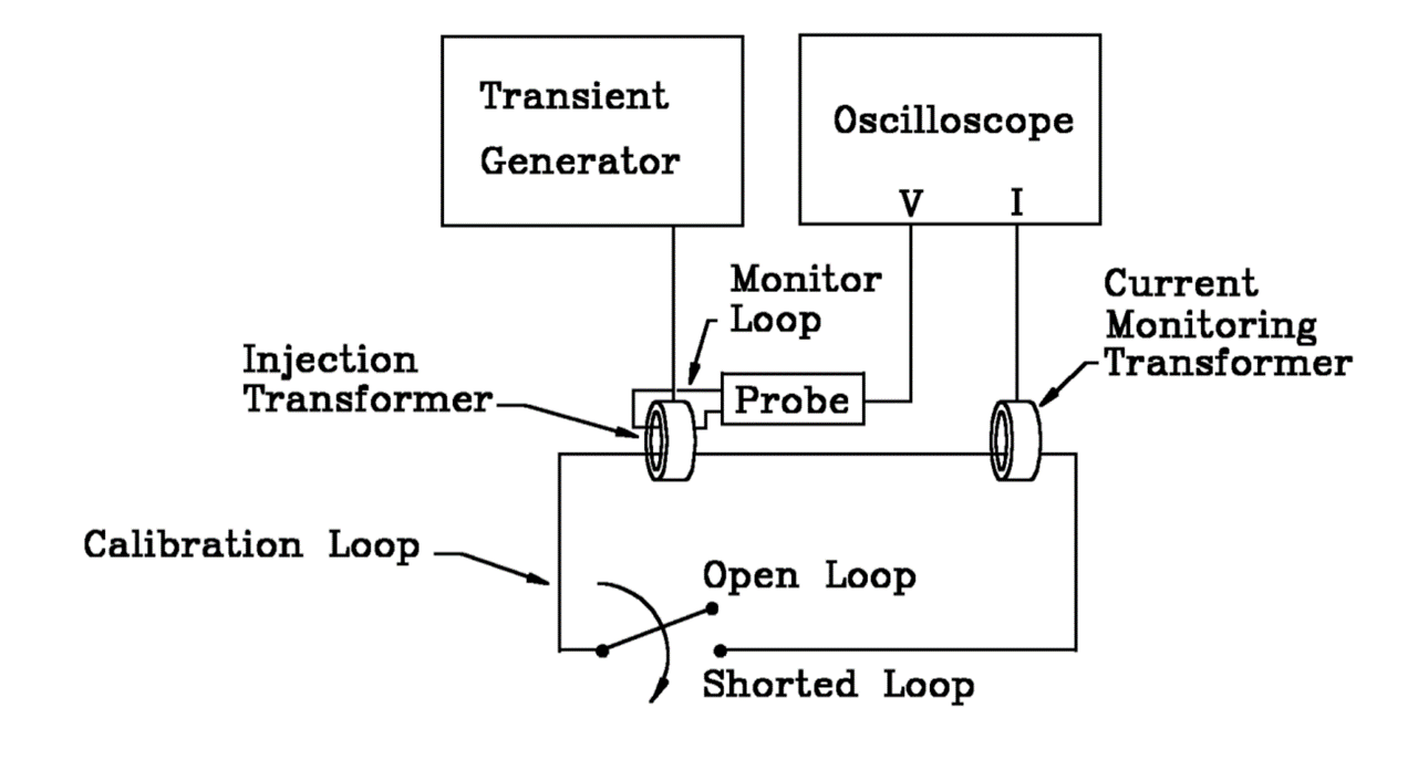
1、Calibration diagram:
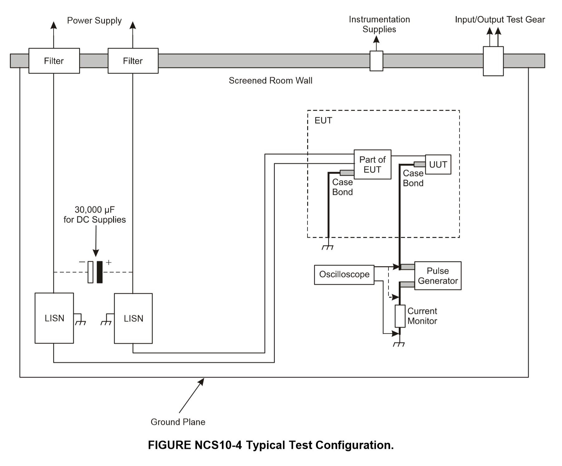
2、Test diagram:

Standard

  • MIL-STD-461G
  • AECTP 250
  • AECTP 500
  • RTCA/DO-160G S22

Specifications


Technical Parameters – LSS 160SM6
W1
Coupling Mode Cable Induction (CI) Ground Injection (GI)
Module Selection Wave 1-CI/GI Wave 1-CI/GI
Current Waveform 6.4 μs ± 20% / 69 μs ± 20% 6.4 μs ± 20% / 69 μs ± 20%
Single-Stroke 25 A – 1000 A +20%, -0% 25 A – 1000 A +20%, -0%
Multiple-Stroke 25 A – 1000 A +20%, -0% (First stroke);

25 A – 500 A +50%, -0% (Subsequent stroke)

25 A – 1000 A +20%, -0% (First stroke);

25 A – 500 A +50%, -0% (Subsequent stroke)

No. of Subsequent Strokes 1 – 14 adjustable 1 – 14 adjustable
Time Intervals of Subsequent Strokes 10 ms – 200 ms adjustable, uniformity mode or random mode 10 ms – 200 ms adjustable, uniformity mode or random mode
Polarity +, – +, –
Current Coupling Device LCVT-L3 LCVT-L3
No. of Tests 1 – 99 1 – 99
Test Repetition 30 s – 99 s (the min. depends on the output amplitude) 30 s – 99 s (the min. depends on the output amplitude)
EUT Load Capacity / AC 230 V, 16 A, 50 Hz / 60 Hz, & DC
Technical Parameters –LSS 160SM6
W4
Coupling Mode Cable Induction (CI) Ground Injection (GI)
Module Selection Wave 4-CI/GI Wave 4-CI/GI
Voltage Waveform 6.4 μs ± 20% / 69 μs ± 20% 6.4 μs ± 20% / 69 μs ± 20%
Single-Stroke 10 V – 1,700 V +20%, -0% 10 V – 1,700 V +20%, -0%
Multiple-Stroke 10 V – 1,700 V +20%, -0% (First stroke);

10 V – 500 V +50%, -0% (Subsequent stroke)

10 V – 1,700 V +20%, -0% (First stroke);

10 V – 500 V +50%, -0% (Subsequent stroke)

No. of Subsequent Strokes 1 – 14 adjustable 1 – 14 adjustable
Time Intervals of Subsequent Strokes 10 ms – 200 ms adjustable, uniformity mode or random mode 10 ms – 200 ms adjustable, uniformity mode or random mode
Polarity +, – +, –
Current Coupling Device LCVT-L3 LCVT-L3
No. of Tests 1 – 99 1 – 99
Test Repetition 10 s – 99 s (the min. depends on the output amplitude) 10 s – 99 s (the min. depends on the output amplitude)
EUT Load Capacity / AC 230 V, 16 A, 50 Hz / 60 Hz, & DC
Technical Parameters – LSS 160SM6
W4
Coupling Mode Pin Induction (PI)
Module Selection Wave 4-PI
Output Impedance 5 Ω ±10%
Voltage/Current Waveform 6.4 μs ±20% / 69 μs±20%
Single-Stroke 25 V – 800 V +10%, -0% (open-circuit voltage);

5 A – 160 A +10%, -0% (short-circuit current);

Polarity +, –
No. of Tests 1 – 99
Test Repetition 10 s – 99 s (the min. depends on the output amplitude)
EUT Power Sync Synchronized automatically with AC power peak value or 0°~359° (resolution 1°, tolerance less than 10°)
EUT Load Capacity AC 230 V, 800 Hz/td>
Technical Parameters – LSS 160SM6
W5A
Coupling Mode Cable Induction (CI) Ground Injection (GI)
Module Selection Wave 5A-CI/GI Wave 5A-CI/GI
Current Waveform 40 μs ± 20% / 120 μs ± 20% 40 μs ± 20% / 120 μs ± 20%
Single-Stroke 20 A – 2,000 A +20%, -0% 20 A – 2,000 A +20%, -0%
Multiple-Stroke 20 A – 2,000 A +20%, -0% (First stroke);

20 A – 1000 A +50%, -0% (Subsequent stroke)

20 A – 2,000 A +20%, -0% (First stroke);

20 A – 1000 A +50%, -0% (Subsequent stroke)

No. of Subsequent Strokes 1 – 14 adjustable 1 – 14 adjustable
Time Intervals of Subsequent Strokes 10 ms – 200 ms adjustable, uniformity mode or random mode 10 ms – 200 ms adjustable, uniformity mode or random mode
Polarity +, – +, –
Current Coupling Device LCVT-L3 LCVT-L3
No. of Tests 1 – 99 1 – 99
Test Repetition 30 s – 99 s (the min. depends on the output amplitude) 30 s – 99 s (the min. depends on the output amplitude)
EUT Load Capacity / AC 230 V, 16 A, 50 Hz / 60 Hz, & DC
Technical Parameters – LSS 160SM6
W5B
Coupling Mode Cable Induction (CI) Ground Injection (GI)
Module Selection Wave 5B-CI/GI Wave 5B-CI/GI
Current Waveform 50 μs ± 20% / 500 μs ± 20% 50 μs ± 20% / 500 μs ± 20%
Single-Stroke 25 A – 2,000 A +20%, -0% 25 A – 2,000 A +20%, -0%
Multiple-Stroke 25 A – 2,000 A +20%, -0% (First stroke);

25 A – 1000 A +50%, -0% (Subsequent stroke)

25 A – 2,000 A +20%, -0% (First stroke);

25 A – 1000 A +50%, -0% (Subsequent stroke)

No. of Subsequent Strokes 1 – 14 adjustable 1 – 14 adjustable
Time Intervals of Subsequent Strokes 30 ms – 200 ms adjustable, uniformity mode or random mode 30 ms – 200 ms adjustable, uniformity mode or random mode
Polarity +, – +, –
Current Coupling Device LCVT-L3 LCVT-L3
No. of Tests 1 – 99 1 – 99
Test Repetition 30 s – 99 s (the min. depends on the output amplitude) 30 s – 99 s (the min. depends on the output amplitude)
EUT Load Capacity / AC 230 V, 16 A, 50 Hz / 60 Hz, & DC
Technical Parameters – LSS 160SM6
W5A
Coupling Mode Pin Induction (PI)
Module Selection Wave 5A-PI
Output Impedance 1 Ω ±10%
Voltage/Current Waveform 40 μs ± 20% / 120 μs ± 20%
Single-Stroke 25 V – 800 V +10%, -0% (open-circuit voltage);

25 A – 800 A +10%, -0% (short-circuit current);

Polarity +, –
No. of Tests 1 – 99
Test Repetition 30 s – 99 s (the min. depends on the output amplitude)
EUT Power Sync Synchronized automatically with AC power peak value or 0°~359° (resolution 1°, tolerance less than 10°)
EUT Load Capacity AC 230 V, 800 Hz/td>
Technical Parameters – LSS 160SM6
W5B
Coupling Mode Pin Induction (PI)
Module Selection Wave 5B-PI
Output Impedance 1 Ω ±10%
Voltage/Current Waveform 50 μs ± 20% / 500 μs ± 20%
Single-Stroke 25 V – 800 V +10%, -0% (open-circuit voltage);

25 A – 800 A +10%, -0% (short-circuit current);

Polarity +, –
No. of Tests 1 – 99
Test Repetition 30 s – 99 s (the min. depends on the output amplitude)
EUT Power Sync Synchronized automatically with AC power peak value or 0°~359° (resolution 1°, tolerance less than 10°)
EUT Load Capacity AC 230 V, 800 Hz/td>
Technical Parameters – LIS 100B
W2
Coupling Mode Cable Induction (CI)
Rise Time < 100 ns
Duration 6.4 μs ±20%
Single-Stroke 25 V – 1,600 V +20%, -0%
Multiple-Stroke 25 V – 750 V +20%, -0% (First stroke);

12.5 V – 350 V +50%, -0% (Subsequent Stroke)

Test Repetition 1.5 s – 60 s (the min. depends on the output amplitude)
Polarity +, –
High-Frequency Voltage Coupling Transformer LVT-2
Technical Parameters – LIS 100B
W3
Coupling Mode Pin Induction (PI)
Module Selection W3 – 1 MHz
Output Impedance 25 Ω
Voltage/Current Repetition 1 MHz ±20%
Attenuation of 5th Stroke 25% – 75%
Single-Stroke 50 V – 2000 V +10%, -0%;

2 A – 80 A +10%, -0% (short-circuit current)

Test Repetition 1.5 s – 60 s (the min. depends on the output amplitude)
Polarity +, –
Phase Sync. 0° – 359°, 1° step
EUT Load Capacity AC 230 V, DC ±50 V, 800 Hz
Technical Parameters – LIS 100B
W3
Coupling Mode Cable Induction (CI) Ground Injection (GI)
Module Selection W3 – 1 MHz W3 – 10 MHz
Voltage/Current Repetition 1 MHz ±20% 10 MHz ±20%
Attenuation of 5th Stroke 25% – 75% 25% – 75%
Single-Stroke 50 V – 2000 V +20%, -0% 50 V – 1600 V +20%, -0%
Multiple-Stroke 50 V – 2000 V +20%, -0% (First stroke);

25 V – 1000 V +50%, -0% (Subsequent stroke)

50 V – 1600 V +20%, -0% (First stroke);

25 V – 800 V +50%, -0% (Subsequent stroke)

Multiple-Burst 50 V – 900 V +20%, -0% 50 V – 900 V +20%, -0%
Test Repetition 1.5 s – 60 s (the min. depends on the output amplitude) 1.5 s – 60 s (the min. depends on the output amplitude)
Polarity +, – +, –
High-Frequency Voltage Coupling Transformer LVT-2 LVT-2
Technical Parameters – LIS 100B
W2
Coupling Mode Cable Induction (CI)
Rise Time < 100 ns
Duration 6.4 μs ±20%
Single-Stroke 25 V – 1,600 V +20%, -0%
Multiple-Stroke 25 V – 750 V +20%, -0% (First stroke);

12.5 V – 350 V +50%, -0% (Subsequent Stroke)

Test Repetition 1.5 s – 60 s (the min. depends on the output amplitude)
Polarity +, –
High-Frequency Voltage Coupling Transformer LVT-2
Technical Parameters – LIS 100B
W6
Coupling Mode Cable Induction (CI)
Current Waveform 5 A-75 A
Rise Time 0.25 μs ±20%
Pulse Width 4 μs ±20%
Test Repetition 3 s-10 s(the min. depends on the output amplitude)
High-Frequency Voltage Coupling Transformer LVT-3
General Parameters
Power Supply Voltage AC 110 V / 220 V ±10%, 50 Hz /60 Hz ±5% (Default AC 220 V 50 Hz in mainland China)
Max Power 200 W
Operating Temp. 15 ℃ – 35 ℃
Operating Humidity 45% – 75%
Operating Air Pressure 86 kPa – 106 kPa

Downloads

Adobe PDF

Reviews

There are no reviews yet.

Be the first to review “Indirect Lightning Induced Transient”

Your email address will not be published. Required fields are marked *