Indirect Lightning Induced Transient

Model:LSS 160SM8

The LSS 160SM8 test system is capable of generating waveforms 1,4 and 5A/5B specified in RTCA/DO-160 Section 22, test level is from 1 to 5 for pins injection test and cable bundle test.

In Stock
Enquire Now

Description

When an aircraft is flying in severe convection environment, it will be frequently affected by lightning stroke, which will generate transient induced voltage or current on circuits and cables of airborne equipment, such phenomenon is called indirect lightning effect. It may make the aircraft get out of control, even bring about fuselage fire and other serious accidents. For safety reasons, the airborne equipment must be designed properly and tested completely to ensure the system and equipment with critical safety function to perform normally and its flight security when the aircraft is influenced by lightning stroke.
The LSS 160SM8 test system is capable of generating waveforms 1,4 and 5A/5B specified in RTCA/DO-160 Section 22, test level is from 1 to 5 for pins injection test and cable bundle test; in addition, the system also meets the A \ B \ C \ D class EUT pulse injection level defined in GJB 8848-2016, as well as multiple related standards such as MIL-STD-461G CS 117 lightning induction transient conduction sensitivity test.
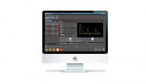
The ETS 160MB test system includes various test auxiliary equipment to make it convenient to conduct tests, such as coupling transformer, power blocking device, transient blocking device, external DC capacitor etc. What’s more, the Corelab software is also available for test remote control, which makes your test easy and convenient.

Features:

  • Modular design, the waveform module is detachable;
  • Capable of performing pins injection test and cable bundle test;
  • Capable of generating waveforms 1, 4 and 5A/5B;
  • 5.7 inch color touch screen with easy and distinct operation control;
  • Phase synchronization function in signal pins & power pins -direct injection method;
  • Corelab software are available for remote control.

Standard

  • GJB 8848-2016
  • AECTP 250
  • AECTP 500
  • RTCA/DO-160G S22
  • MIL-STD-461G CS117
  • HB 6167.24

Specifications

Technical Parameters—Current Waveform 1

Cable Bundle and Ground Induction

For Tests As Per DO-160G S22, MIL-STD-461G CS117(WF2/1)
Coupling Mode Cable Induction (CI)
Ground injection (GI)
Output Module W1 CI/GI
Current Waveform 1 6.4 μs ± 20 % / 69 μs ± 20 %
Single Stroke Output 50 A ~ 4200 A (-0%~+20%);

Output impedance≤0.5 Ω

Multiple Stroke Output 50 A ~2000 A (-0%~+20%) (first stroke); Output Impedance≤0.5 Ω
25 A ~ 1000 A (-0%~+50%) (subsequent stroke);

Output Impedance≤0.5 Ω

Number of Subsequent Pulses 1 ~ 14
Interval Time of Subsequent Pulses 10 ms ~ 200 ms,

random mode is available

Polarity positive or negative
Number of Test Times 1 ~ 99
Test Repetition 10 s ~ 99 s (shortest time depends on output amplitude)
Coupler LCT- L5B
Maximum EUT Power Supply Cable Induction (CI):none

Ground Injection (GI):

AC 230 V / 32 A 50/60 Hz;

DC 230 V/32 A

Output Module WAVE 1 CI/GI IH
Single Stroke Output 50 A ~ 3200 A (-0%~+20%);
Multiple Stroke Output 50 A ~ 1600 A (-0%~+20%) (first stroke)
25 A ~ 800 A (-0%~+50%) (subsequent stroke);
Technical Parameters—Voltage Waveform 5A

Signal Pins & Power Pins Direct Injection

For tests as per DO-160G S22
Coupling Mode Pins direct injection(PDI)
Output Module W5A PI
Output Impedance 1 Ω ± 10 %
Voltage/

Current Waveform 5A

40 μs ± 20 % / 120 μs ± 20 %
Output Voltage 50 V ~ 3000 V (-0%~+10%) (open circuit)
Output Current 50 A ~ 3000 A (-0%~+10%) (short circuit)
Polarity positive or negative
Number of Test Times 1 ~ 99
Test Repetition 10 s ~ 99 s (shortest time depends on output amplitude)
EUT Power Supply Max. 230 V
EUT Power Frequency Max. 800 Hz
Power Blocking Device Greater than peak value of signal or power voltage (optional)
Technical Parameters—Voltage Waveform 4

Signal Pins & Power Pins Direct Injection

For Tests As Per DO-160G S22
Coupling Mode Pins Direct Injection (PDI)
Output Module W4 PI
Output Impedance 5 Ω ± 10 %
Voltage/Current Waveform 4 6.4 μs ± 20 % / 69 μs ± 20 %
Output Voltage 50 V ~ 3000 V (-0%~+10%), (open circuit)
Open Current 10 A ~ 600 A (-0%~+10%),

(short circuit)

Polarity positive or negative
Number of Test Times 1 ~ 99
Test Repetition 10 s ~ 99 s (shortest time depends on output amplitude)
EUT Power Supply Max. 230 V
EUT Frequency Max. 800 Hz
Power Blocking Device Greater than peak value of signal or power voltage (optional)
Technical Parameters—Voltage Waveform 4

Cable Bundle and Ground Injection

For tests as per DO-160G S22
Coupling Mode Ground Injection (GI)
Output Module W4 CI/GI
Voltage Waveform 4 6.4 μs ± 20 % / 69 μs ± 20 %
Single Stroke Output 50 V ~ 3000 V (-0%~+20%);

Output Impedance≥0.5 Ω

Multiple Stroke Output 25 V ~ 1000 V (-0%~+20%) (first stroke);

Output Impedance≥0.5 Ω

10 V ~ 500 V (-0%~+50%) (subsequent stroke);

Output Impedance≥0.5 Ω

Number of Subsequent pulses 1 ~ 14
Interval Time of Subsequent Pulses 10 ms ~ 200 ms,

random mode is also available

Polarity positive or negative
Number of Test Times 1 ~ 99
Test Repetition 10 s ~ 99 s (shortest time depends on output amplitude)
Maximum EUT Power Supply Cable induction (CI):none

Ground injection (GI):

AC 230 V / 32 A 50/60 Hz;

DC 230 V/32 A

Coupler LVT-L5B
Technical Parameters—Voltage Waveform 5A

Cable Bundle and Cable Injection

For tests as per DO-160G S22, MIL-STD-461G CS117(WF4/5A)
Coupling Mode Cable Induction (CI)
Ground injection (GI)
Output Module W5A CI/GI
Voltage Waveform 5A 40 μs ± 20% / 120 μs ± 20%
Single Stroke Output 50 A ~ 10000 A (-0%~+20%);

Output impedance≤0.3 Ω

Multiple Stroke Output 50 A ~ 2000 A (-0%~+20%) (first stroke);

Output impedance≤0.3 Ω

25 A ~ 1000 A (-0%~+20%) (first stroke);

Output impedance≤0.3 Ω

Number of Subsequent pulses 1 ~ 14
Interval Time of Subsequent Pulses 10 ms ~ 200 ms,

random mode is also available

Polarity positive or negative
Number of Test Times 1 ~ 99
Test Repetition 10 s ~ 99 s (shortest time depends on output amplitude)
Coupler LVT-5B
Maximum EUT Power Supply Cable induction (CI):none

Ground injection (GI):

AC 230 V / 32 A 50/60 Hz;

DC 230 V/32 A

Technical Parameters—Voltage Waveform 5B

Signal Pins & Power Pins Direct Injection

For tests as per DO-160G S22
Coupling Mode Pins Direct Injection(PDI)
Output Module W5B PI
Output Impedance 1 Ω ± 10 %
Voltage/

Current Waveform 5B

50 μs ± 20 % / 500 μs ± 20 %
Single Stroke Output 50 V ~ 1600 V (-0%~+10%) (open circuit)
50 V ~ 1600 V (-0%~+10%) (short circuit)
Polarity positive or negative
Number of Test Times 1 ~ 99
Test Repetition 10 s ~ 99 s (shortest time depends on output amplitude)
EUT Power Supply Max. AC/DC 230 V
EUT Power Frequency Max. 800 Hz
Power Blocking Device Greater than peak value of signal or power voltage (optional)
Technical Parameters—Current Waveform 5B

Cable Bundle and Cable Induction

For tests as per DO-160G S22
Coupling Mode Cable Induction (CI)
Ground injection (GI)
Output Module W5B CI/GI
Current Waveform 5B 50 μs ± 20 % / 500 μs ± 20 %
Single Stroke Output 50 A ~ 5000 A (-0%~+20%);

Output Impedance≤0.3 Ω

Multiple Stroke Output 50 A ~ 2000 A (-0%~+20%) (first stroke);

Output Impedance≤0.3 Ω

25 A ~ 1000 A (-0%~+50%) (subsequent stroke);

Output Impedance≤0.3 Ω

Number of Subsequent pulses 1 ~ 14
Interval Time of Subsequent Pulses 30 ms ~ 200 ms,random mode is also available
Polarity positive or negative
Number of Test Times 1 ~ 99
Test Repetition 10 s ~ 99 s (shortest time depends on output amplitude)
Coupler LCT- L5B
Maximum EUT Power Supply Cable induction (CI):none

Ground injection (GI):

AC 230 V / 32 A 50/60 Hz;

DC 230 V/32 A

List Of Waveform Module and Test Type
Waveform Module Test type
W1 CI/GI;

W1-CI/GI-IH

Current waveform 1 – cable bundle cable induction test

Current waveform 1 – cable bundle ground injection test

W4 PI Voltage waveform 4 – signal pins & power pins direct injection method
W4 CI/GI Voltage waveform 4 – cable bundle cable induction test

Voltage waveform 4 – cable bundle ground injection test

W5A PI Voltage waveform 5A – signal pins & power pins direct injection method
W5A CI/GI Current waveform 5A – cable bundle cable induction test

Current waveform 5A – cable bundle ground injection test

W5B PI Voltage waveform 5B – signal pins & power pins direct injection method
W5B CI/GI Current waveform 5B – cable bundle cable induction test

Current waveform 5B – cable bundle ground injection test

Technical Parameters—Intermediate Width Pulse (IP) Waveform 1
For Tests As Per GJB 8848
Coupling Mode Ground injection (GI)
Output Module W1 I
Current Waveform 6.4 μs ± 20% / 69 μs ± 20%
Output current 50 A ~ 4000 A (± 10%);
Polarity positive or negative
Number of Test Times 1 ~ 99
Test Repetition 8 s ~ 99 s (shortest time depends on output amplitude)
Coupler LCT- L5B
Technical Parameters—Intermediate

width pulse (IP) Waveform 4

For Tests As Per GJB 8848
Coupling Mode Ground Injection (GI)
Output Module W4 V
Waveform 6.4 μs ± 20% / 69 μs ± 20%
Voltage Output 50 V ~ 2500 V (± 10%);
Polarity positive or negative
Number of Test Times 1 ~ 99
Test Repetition 10 s ~ 99 s (shortest time depends on output amplitude)
Technical Parameters— Long Pulse (LP) Waveform 5A
For Tests As Per GJB 8848
Coupling Mode Ground Injection (GI)
Output Module W5A V
Waveform 40 μs ± 20% / 120 μs ± 20%
Voltage Output 1000 V ~ 2500 V (± 10%);
Polarity positive or negative
Number of Test Times 1 ~ 99
Test Repetition 10 s ~ 99 s (shortest time depends on output amplitude)
Technical Parameters— Long Pulse (LP) Waveform 5A
For Tests As Per GJB 8848
Coupling Mode Ground Injection (GI)
Output Module W5A I
Waveform 40 μs ± 20% / 120 μs ± 20%
Output current 1000 A ~ 14000 A (± 10%);
Polarity positive or negative
Number of Test Times 1 ~ 99
Test Repetition 10 s ~ 99 s (shortest time depends on output amplitude)
Coupler LCT- L5B
Technical Parameters— Long Pulse (LP) Waveform 5B
For Tests As Per GJB 8848
Coupling Mode Ground Injection (GI)
Output Module W5B V
Waveform 50 μs ± 20% / 500 μs ± 20%
Voltage Output 1000 V ~ 2200 V (± 10%);
Polarity positive or negative
Number of Test Times 1 ~ 99
Test Repetition 10 s ~ 99 s (shortest time depends on output amplitude)
Technical Parameters— Long Pulse (LP) Waveform 5B
For Tests As Per GJB 8848
Coupling Mode Ground Injection (GI)
Output Module W5B I
Waveform 50 μs ± 20% / 500 μs ± 20%
Output current 1000 A ~ 10000 A (± 10%);
Polarity positive or negative
Number of Test Times 1 ~ 99
Test Repetition 8 s ~ 99 s (shortest time depends on output amplitude)
Coupler LCT- L5B
General parameters
Display 5.7” TFT touch screen
Working Power 220 V,±10%,50/60Hz
Fuse 10 A
User’s Memory Space Infinite (PC)
Communication Mode Ethernet LAN, RJ45
Working Status Indication LED indication and LCD display on front panel
Grounded Connection Flat earth line
Waveform Output Terminal Banana plug line
Dimension 35U cabinet
Weight Approx. 320 kg
Ambient Temperature 15 ℃ ~ 35 ℃
Relative Humidity 45% ~ 75%
Atmospheric Pressure 86 kPa ~ 106 kPa

Downloads

Adobe PDF

Reviews

There are no reviews yet.

Be the first to review “Indirect Lightning Induced Transient”

Your email address will not be published. Required fields are marked *