Description
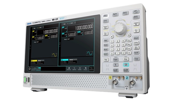
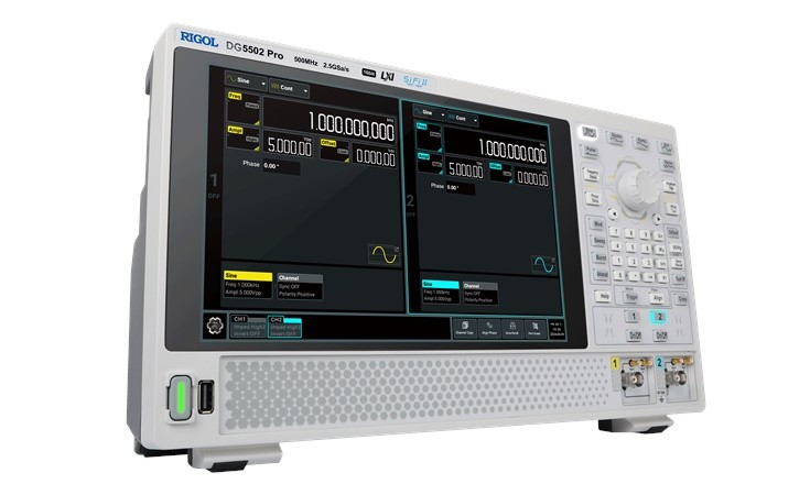
DG5000 Pro series function/arbitrary waveform generator provides up to 2.5 GSa/s sample rate and 64 Mpts/CH memory depth (standard). It is a cost-effective dual-channel function/arbitrary waveform generator that combines multiple functions including Function Generator, Arbitrary Waveform Generator, Noise Generator, Pulse Generator, Harmonic Generator, Analog/Digital Modulator and Counter.
The 10.1″ touch screen allows a clear view on measurement results. Its provides USB and LAN interfaces (standard) as well as the Web Control function for you to control the instrument directly, bringing smoother interaction.
| Model | DG5252 Pro | DG5352 Pro | DG5502 Pro |
|---|---|---|---|
| Max. Frequency | 250 MHz | 350 MHz | 500 MHz |
| Resolution | 1 µHz | 1 µHz | 1 µHz |
| Sample Rate | 2.5 GSa/s | 2.5 GSa/s | 2.5 GSa/s |
| Vertical Resolution | 16 bits | 16 bits | 16 bits |
| Waveform Memory Depth | 64 Mpts (standard), 128 Mpts (optional) | 64 Mpts (standard), 128 Mpts (optional) | 64 Mpts (standard), 128 Mpts (optional) |
| Max Amplitude | 10 Vpp < 100 MHz | 10 Vpp < 100 MHz | 10 Vpp < 100 MHz |
| Frequency Counter | up to 1 GHz | up to 1 GHz | up to 1 GHz |
| Channels | 2 | 2 | 2 |
You will find the specifications of the Rigol DG5000 Pro series here.
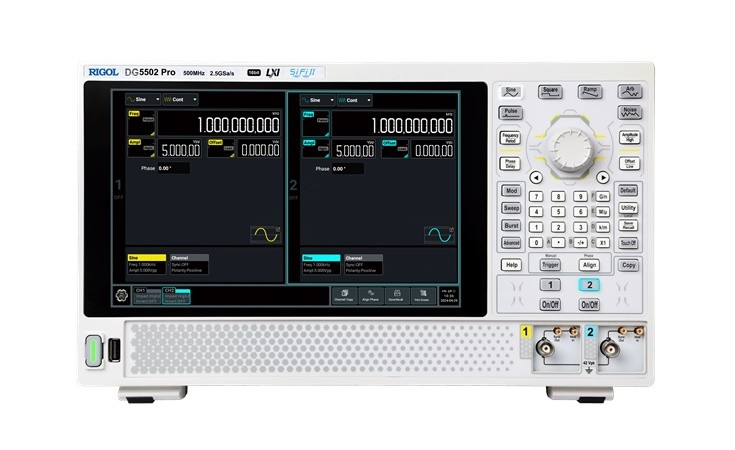
Frontansicht
1 – 10.1-inch Touch Screen
2 – Output Mode Selection Area
3 – Frequency/Period and Phase/Delay Toggle Keys
4 – Basic Waveform Selection Area
5 – Amplitude/High Level and Offset/Low Level Toggle Keys
6 – Parameter Input Area (Knob, Arrow Keys, and Numeric Keypad)
7 – Quick Operation Key
8 – Channel Output Control Area
9 – CH2 Sync Output Connector, Modulation Input Connector
10 – CH2 Output Connector
11 – CH1 Sync Output Connector, Modulation Input Connector
12 – CH1 Output Connector
13 – Help Key, Manual Trigger Key, Align Phase Key
14 – USB HOST Interface
15 – Power Key
![]()
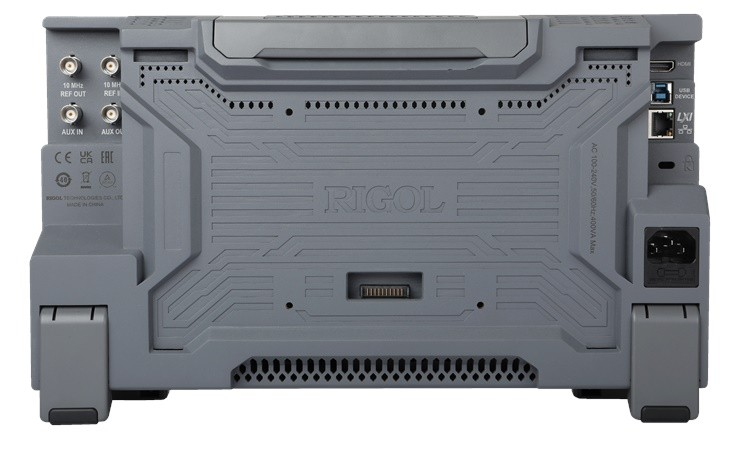
Rear View
1 – 10 MHz Reference Output Connector
2 – 10 MHz Reference Input Connector
3 – Mounting Screw Holes (VESA 100 x 100)
4 – HDMI Interface
5 – USB DEVICE Interface
6 – LAN Interface
7 – Security Lock Hole
8 – AC Power Socket
9 – Fuse
10 – Battery Holder Connector
11 – Auxiliary Output Connector
12 – External Trigger Input Connector
![]()
User Interface
1 – Basic Waveform Drop-down Button
2 – Output Mode Drop-down Button
3 – Parameter Configuration Area
4 – Notification Area
5 – Screen Capture Key
6 – Store/Recall Key
7 – Align Phase Function Key
8 – Channel Copy Function Key
9 – Channel Tab
10 – Channel Labels
11 – Function Navigation Icon
12 – Waveform Tab
13 – Channel Identifier
![]()
Reviews
There are no reviews yet.