Combination Wave Simulator CWS 120CT

Model:CWS 120CT

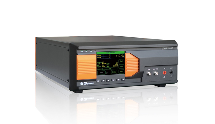
CWS 120CT is a high-end testing equipment specially designed to simulate the phenomenon of low-voltage surge pulse interference.

In Stock
Enquire Now

Description

CWS 120CT is a high-end testing equipment specially designed to simulate the phenomenon of low-voltage surge pulse interference. It is suitable for testing surge protection devices (such as TVS tubes, TSPDs, SIDAC, surge suppressors, etc.), and can also be used for wafer or package level surge immunity testing. The output voltage range is adjustable from 1V to 1200V, and the technical parameters fully meet the requirements of IEC/EN 61000-4-5 and GB/T 17626.5 standards. The CWS 120CT design is based on the third-generation intelligent control platform, which has advantages such as high system integration, intelligent control, easy operation, and saving testing time.

Features:

  • 5.7-inch color touch screen front panel operation.
  • Complies with IEC/EN61000-4-5 and GB/T 17626.5 standards.
  • Output voltage from 1 V to 1200 V.
  • Standard source output impedance 2 Ω, 12 Ω, 42 Ω.
  • The output impedance of the communication wave source is 15 Ω and 40 Ω.
  • Built in four types of coupling and decoupling networks.
  • EUT load capacity 40 V DC 10 A.
  • Real time display of output peak voltage and current peak size.
  • Test scheduling function, easy to operate.
  • Ethernet, RJ45 interface, used for PC remote control and printing test reports.
  • PC control software CoreLab is optional.
Standard

  • IEC 61000-4-5
  • GB/T 17626.5
  • EN 61000-4-5

Specifictions

Complies With IEC 61000-4-5 Surge Immunity Test
1.2/50 μs 8/20 μs Technical Parameters
Test Voltage Range 1 V – 1200 V ± 10%
Voltage Waveform Front time:1.2 μs ± 30%

Half peak time:50 μs ± 20%

Test Current Range 0.5 A-600 A ±10%(2 Ω)
Current Waveform Front time:8 μs ± 20%

Half peak time:20 μs ± 20%

Output Impedance 2 Ω、12 Ω、42 Ω
Polarity Positive, negative, alternating positive and negative
Pulse Period 1-9999 s
Number Of Experiments 1-9999 times
Trigger Method Automatic, manual, external triggering
Experimental Mode Schedule experimental parameters
Coupling/

Decoupling Methods

C/L、D/L、C/D、D/D

C represents capacitance, L represents inductance, and D represents diode

EUT Carrying Capacity 40 V DC 10 A
Display Peak voltage and peak current display function
Complies With IEC 61000-4-5 Surge Immunity Test
10/700 μs 5/320 μs Technical Parameters
Test Voltage Range 1 V – 1200 V ±10%
Voltage Waveform Front time:10 μs ± 30%

Half peak time:700 μs ± 20%

Test Current Range 0.025 A – 30 A ± 10%
Current Waveform Front time:5 μs ± 20%

Half peak time:320 μs ± 20%

Output Impedance 15 Ω、40 Ω
Polarity Positive, negative, alternating positive and negative
Pulse Period 1-9999 s
Number Of Experiments 1-9999 times
Trigger Method Automatic, manual, external triggering
Experimental Mode Schedule experimental parameters
General Parameters
Display Screen 5.7 inch TFT color touch screen
Working Voltage Range AC 110 V/220 V,±10%,50/60 Hz
Fuse 6 A
Maximum Power Consumption 200 W
Communication methods Ethernet
Instrument Working Status Indication Front panel LED indication, LCD display
Failure Detection When the failure occurs, the front panel LCD displays and interrupts instrument operation
Chassis Size

(Width * Height * Depth)

4U chassis

(450 mm*190 mm*620 mm)

Weight Approximately 25 kg
Environment Temperature 15℃ – 35℃
Relative Temperature 45% ~ 75%
Barometric Pressure 86 kPa~106 kPa

Downloads

Adobe PDF

Reviews

There are no reviews yet.

Be the first to review “Combination Wave Simulator CWS 120CT”

Your email address will not be published. Required fields are marked *