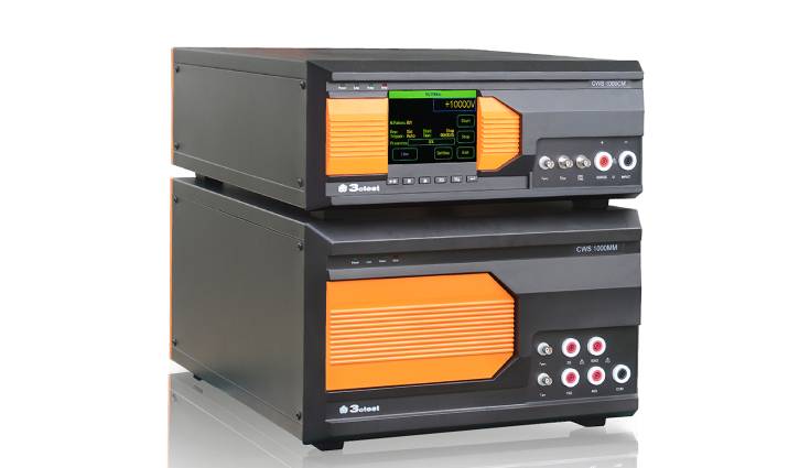
Combination Wave Surge Immunity

Model:CWS 1000CM, CWS 1000MM

Combination wave surge immunity test simulator CWS 1000CM/MM is designed to perform combination wave surge immunity tests according to IEC 61000-4-5, capable of generating waveforms of 1.2/50 μs.

In Stock
Enquire Now

Description

CWS 1000CM/MM is designed to perform combination wave surge immunity tests according to IEC 61000-4-5, capable of generating waveforms of 1.2/50 μs, 8/20 μs, 10/700 μs, 5/320 μs, connected to EUT via external CDN. The equipment meets the relevant requirements of CE, CCC etc.

  • 5.7” color touch screen front panel.
  • Mini size, high capacity (up to 10 kV).
  • Capable of generating 1.2/50 μs, 8/20 μs, 10/700 μs, 5/320 μs waveforms as per IEC 61000-4-5.
  • LCD display of surge voltage and current monitoring.
  • Easy to operate with test sequencing and scheduling.
  • External automatic coupling / decoupling network.


Naming Rules:

Equipment Connection Diagram:

Standard

  • IEC 61000-4-5
  • IEC 61643-1
  • GB/T 17626.5
  • GB/T 16927.1
  • ITU-T K.21
  • ITU T K.44

Specifications

Technical Parameters – 1.2/50 μs, 8/20 μs
Test Voltage 0.5 kV –10.0 kV ± 10%
Voltage Tr 1.2 μs ± 30%
Voltage Td 50 μs ± 20%
Test Current 0.25 kA–5.0kA± 10% (2ohm)
Current Tr 8 μs ± 20%
Current Td 20 μs ± 20%
Output Impedance 2 ohm or 12 ohm
Test Interval 6 s – 99 s (the shortest time subject to test voltage)
Measuring Of Peak Voltage Via BNC on Front Panel: 1000V:1V; Results shown on LCD;
Measuring Of Peak Current Via BNC on Front Panel: 100A:1V; Results shown on LCD;
No. Of Tests 1 – 999
Triggering Mode Automatic, manual, or external triggering
Test Method As per standard test requirements
Technical Parameters – 1.2/50 μs
Test Voltage 0.5 kV –10.0 kV ± 10%
Voltage Tr 1.2 μs ± 30%
Voltage Td 50 μs ± 20%
Output Impedance 500 ohm
Test Interval 5 s – 99 s (the shortest time subject to test voltage)
Measuring Of Peak Voltage Via BNC on Front Panel: 1000V:1V; Results shown on LCD;
No. Of Tests 1 – 999
Triggering Mode Automatic, manual, or external triggering
Test Method As per standard test requirements
Technical Parameters – 10/700 μs, 5/320 μs
Test Voltage 0.5 kV –10.0 kV ± 10%
Voltage Tr 10 μs ± 20%
Voltage Td 700 μs ± 20%
Current Tr 5 μs ± 20%
Current Td 320 μs ± 20%
Output Impedance 15 ohm or 40 ohm
Test Interval 11 s – 99 s (the shortest time subject to test voltage)
Measuring Of Peak Voltage Via BNC on Front Panel: 1000V:1V; Results shown on LCD;
Measuring Of Peak Current Via BNC on Front Panel: 100A:1V; Results shown on LCD;
No. Of Tests 1 – 999
Triggering Mode Automatic, manual, or external triggering
Test Method As per standard test requirements
General parameters
Display 5.7” TFT color touch screen
Operating Voltage AC 110V/220V ±10, 50/60Hz
Fuse 6 A
Capacity 200 W
Storage Space Unlimited (PC)
Communication Method Ethernet, RJ45
Safety Circuit Not operating if the open safety circuit is not closed
Error Detection Errors will be shown on LCD while operation will be stopped.
Output Measuring Method Via 1 m co-axial stable
Operating Temperature 15 ℃ – 35 ℃
Operating Humidity 45%-75%
Operating air Pressure 86 kPa-106 kPa
Dimension 19”,

4U (CWS 1000CM) +

6U (CWS 1000MM)

Weight About 40 Kg

Downloads

Adobe PDF

Reviews

There are no reviews yet.

Be the first to review “Combination Wave Surge Immunity”

Your email address will not be published. Required fields are marked *