
Description
Aircraft is vulnerable to lightening direct adhesion in severe convection weather, which will produce over temperature, high voltage and strong electromagnetic force to cause the aircraft to be on fire, corrosion, explosion, structure distortion and strength reduction, etc. The lightening direct effect test system our company independent research and develop is a very complicated pulse current test system, mainly used in lightening direct effect tests for system, components and materials as per national military standards like GJB1389A,GJB3567, also American military standards MIL-STD-464C, ARP5412 and DO160 section23, etc. This system can be used for aircraft, aerospace materials, naval ships, missile, military vehicles and radar.
This lightening direct effect test system includes high voltage attachment points partition test system and high current physical damage test system. High voltage attachment points partition test system can simulate the possibility that equipments like aircraft are lightening attacked in different areas on the surface of aircraft and find the attachment points which are vulnerable to lightening attack. High current physical damage test system can be used to simulate the damage effect of aircraft structure caused by the over temperature and strong electromagnetic force which are produced when the attachment points are suffered to high current.
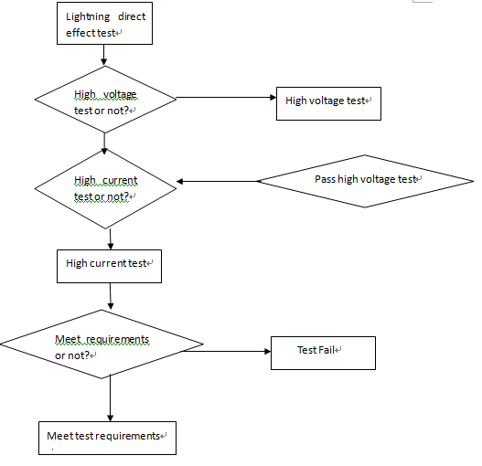
Lightning test flow chart
This system can be configured according to customers test requirements and provide full test solutions.
High voltage attachment points partition test system
This system is composed of three parts including high voltage generator, waveform regulation unit and control measurement system, four kinds of waveforms A, B, C, D are output by regulating different waveform regulation units, meet MIL-STD-464C , DO160 S23 and other standards about direct lightning high voltage test, also used for other similar lightning and withstand voltage tests and research.
Waveform parameter definition
According to MIL-STD-464C and SAE ARP5412, etc, four voltage waveforms shown as below:
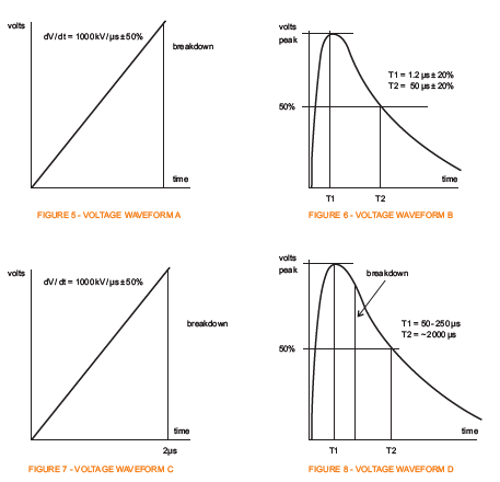
Requirements:- A component rising slope: 1000(-0+50%)kV/μs, rising stop when test device breakdown or flashover and turn to zero. If no flashover for test device, there is no regulation for the waveform drop.
- B component open circuit voltage waveform with rising slope: 1.2μs (±20%) and duration: 50μs(±20%)
- C component the voltage waveform cut off at 1.2μs, no requirements for rise time and peak value.
- D component open circuit voltage waveform with rising slope: 50-250μs and duration: >2000μs. The waveform is used for testing the time characteristic, when the waveform is used for the analysis of lightning attachment area probability, the conclusion is higher than the actual value (please see GJB3567 5.1.1.3).
Technical parameters and features
| Technical parameters of LVG3000 | ||||
| Output waveform | A waveform | B waveform | C waveform | D waveform |
| Front time | 1000(+500)kV/μs | 1.2μs±20% | 2μs±20% | 50-250μs |
| Decay time | — | 50±20% | — | 大于2000 |
| peak efficiency | >90% | >90% | >80% | >60% |
| Charging voltage | 200kV (two-side charging) | |||
| Levels | 15 | |||
| Discharging switch | copper ball , three-gap ignition | |||
| Switch type | linear driving 0~100mm adjustable, accuracy 0.1mm | |||
| Waveform shaping | Form a long wave tail by Crowbar feedback circuit | |||
| General data | ||||
| Power supply | AC220V 100A | |||
| Charging voltage | 20~200kV | |||
| Polarity | +/- | |||
| Voltage measurement | Damped voltage divider | |||
| Features: | ||||
| l LVG 3000 with open style main circuit design and H shaped tower structure to achieve a compact size | ||||
| l Artistic and simple appearance | ||||
| l parallel charging and series discharging by Max generator | ||||
| l Automatically adjust ball gap distance within the charging voltage, 0.1mm resolution adjustable | ||||
| l Automatic safety protection procedure, audible and visual alarm | ||||
High voltage attachment points partition test diagram:
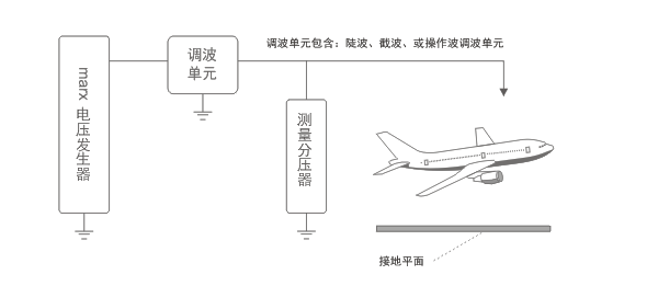
(1)Max voltage generator
(2)Regulation waveform unit
(3)Measurement voltage divider
(4)Regulation waveform unit includes steep slope, chopped wave or operation wave
(5)Grounding plane

Reviews
There are no reviews yet.