
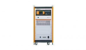
Description
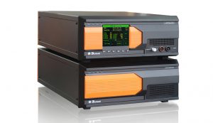
The APS xxxxDSR series is equipped with a four quadrant bipolar amplifier, which simulates various voltage changes on the wiring harness and can generate voltage drops, short-term interruptions, and other voltage changes. The output internal resistance can be adjusted. Built in signal source, users can edit and output any wave through PC software. It can also be used as a battery powered analog and DC voltage source. During laboratory testing, APS xxxxDSR replaced the vehicle battery, generating Pulse 2b, Pulse 4, sine wave noise, and other complex voltage variation waveforms. Very suitable for ISO 7637/16750 conduction transient testing. At the same time, the APS xxxxDSR series complies with numerous international/national standards and automotive manufacturer standards. As a powerful DC power supply, it supports 12V, 24V, 42V, 24V, and 48V system automotive testing.
Features
- Four quadrant bipolar power supply;
- Adjustable output impedance;
- The maximum test voltage can reach 80 V;
- The maximum test current can reach 100 A;
- Automatic compensation function for voltage drop;
- High bandwidth output frequency up to 300 kHz;
- Built in signal source can edit any wave;
- Support AC voltage and current closed-loop testing;
- Can simulate various power supply waveforms, such as superimposed noise, etc;
- Ethernet and RJ45 interfaces, used for PC remote control and printing test reports;
- Output voltage and current monitoring/protection function.
 <
<
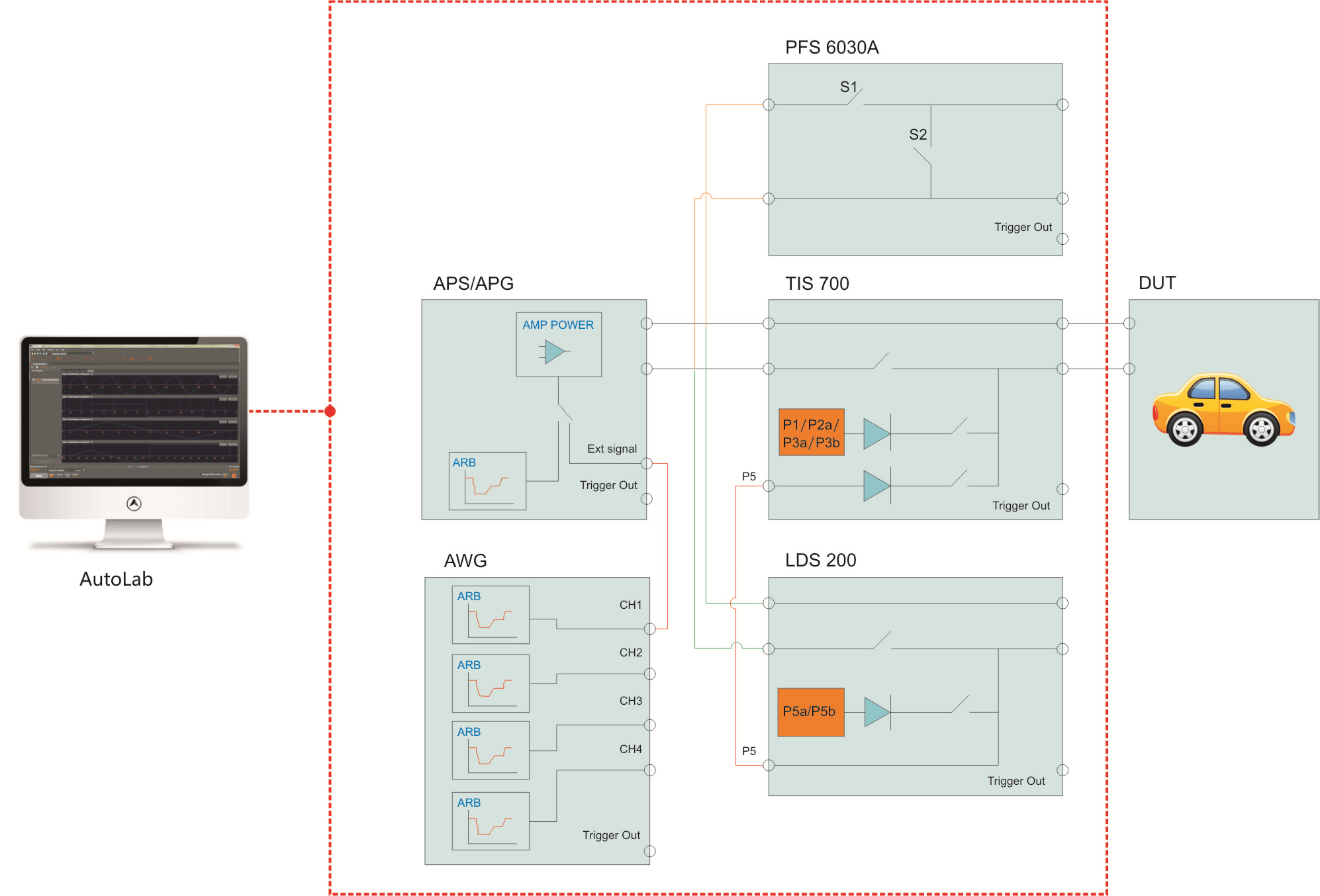
System overall connection diagram
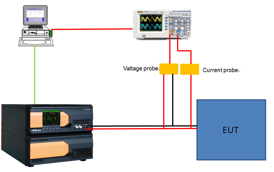
ISO 16750-2 2023 Sweep Frequency Closed Loop Layout
The naming convention for instruments is as follows, using APS 80I100DSR as an example:
APS: Power supply voltage change simulator;
80: Maximum voltage 80V; 40:40V, 60:60V;
I: The level representing negative voltage, D:0V、E:-15V、F:-20V、G:-40V、H:-60V、I:-80V;
100: Output current level, can be divided into 10A, 30A, 50A, 100A;
D: Four-quadrant, bipolar power supply (if D is not included in the model, it is a unipolar power supply);
S: Built in AWG signal generator (without S in the model, there is no built-in signal generator);
R: The output impedance is adjustable (if there is no R in the model, the output impedance is not adjustable).


Reviews
There are no reviews yet.