Vehicle Transient Simulator VTS 200

Model:VTS 200

Vehicle transient simulator VTS 200 is designed according to test requirements of Ford EMC-CS-2009.

In Stock
Enquire Now

Description

Transient simulator VTS 200 is designed according to test requirements of Ford EMC-CS-2009 and FMC1278-2016, capable of generating Pulse A1, A2-1, A2-2, C-1 and C-2 under CI 220, Pulse A2-1 and A2-2 under CI 260 F and RI 130. For RI 130 tests, the BNC co-axial cable is provided for connection with specific test clamps.

Features:

  •  Capable of generating wide range of pulses in compliance with Ford standards;

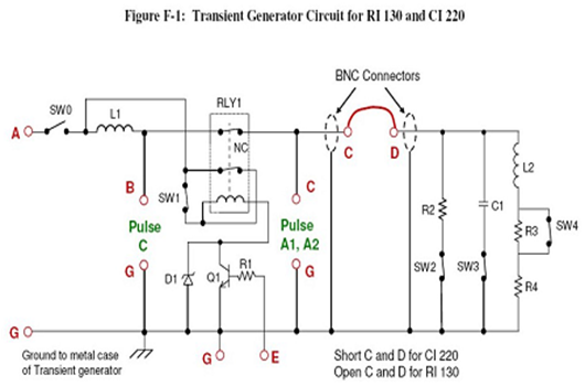
Design Schematic Diagram:
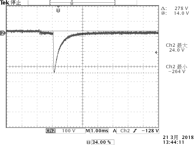
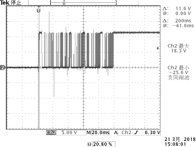
Waveforms:

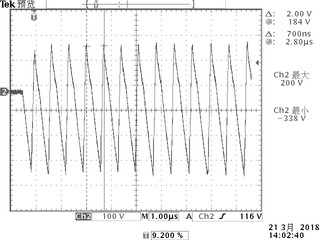
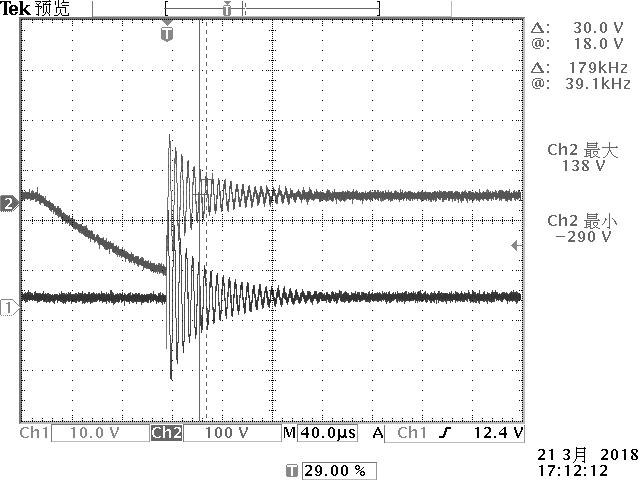
CI 220, Pulse A1, Mode 1

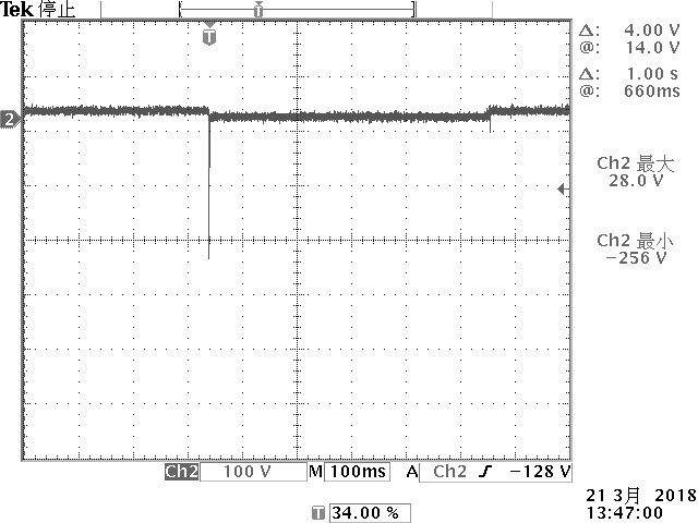
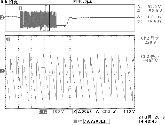
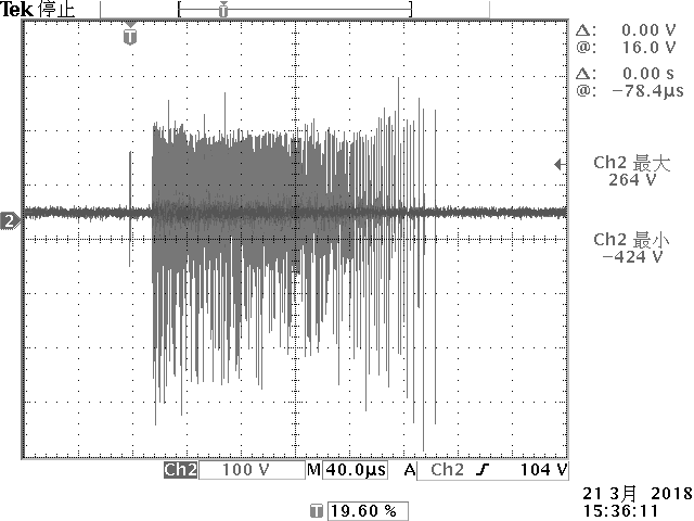
CI 220, Pulse A2-1, Mode 1

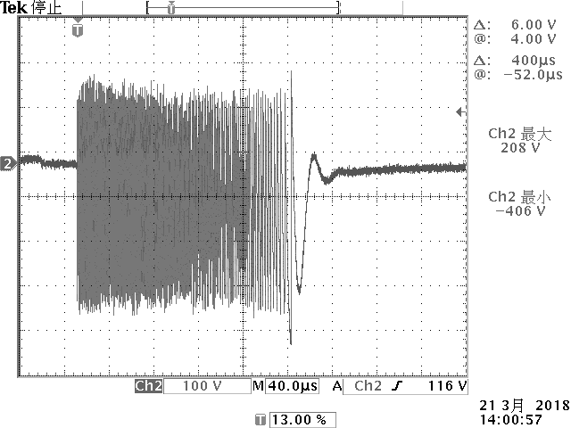
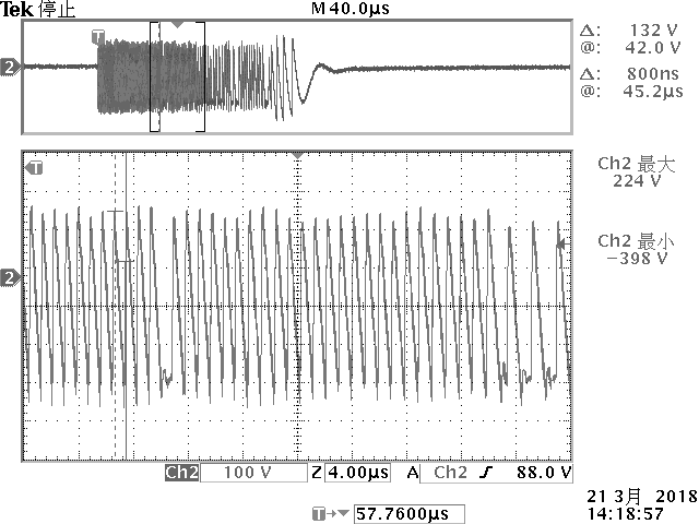
CI 220, Pulse A2-1, Mode 2

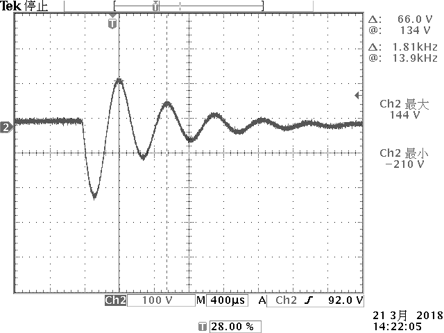
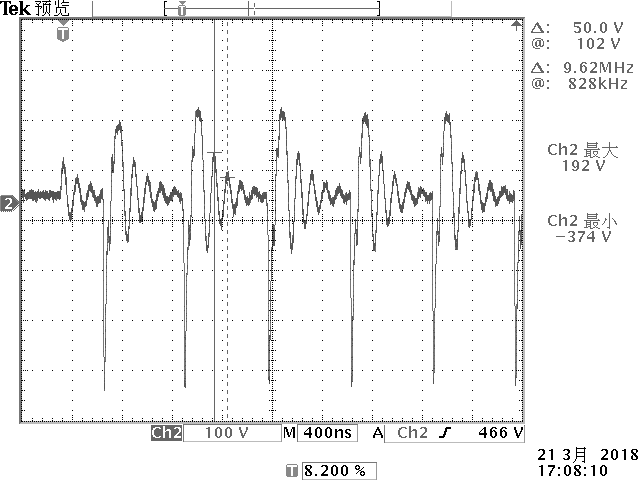
CI 220, Pulse A2-2, Mode 2

CI 220, Pulse C1, Mode 2
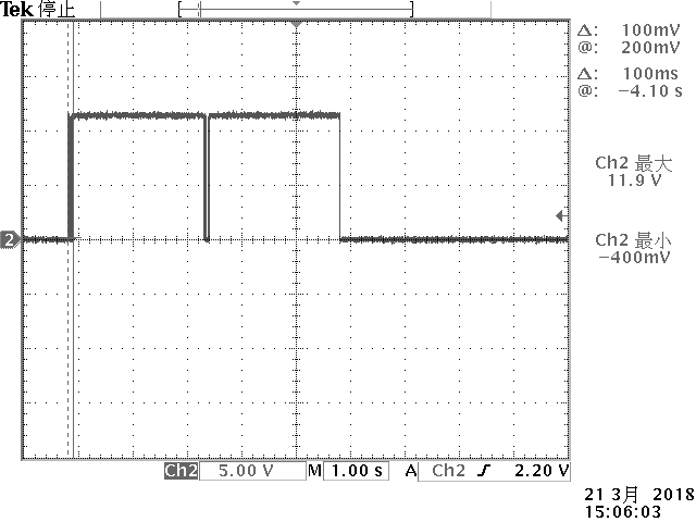
CI 260, Waveform F

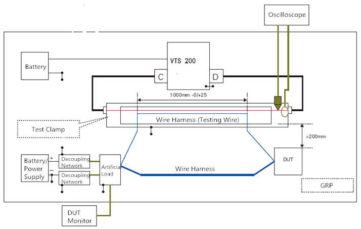
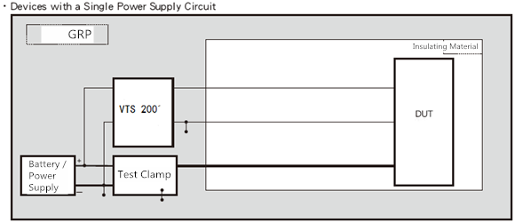
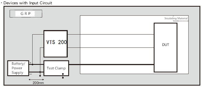
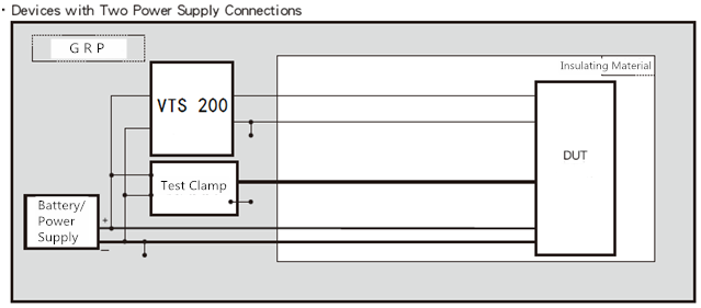
Equipment Connection Diagram

Standard

  • Ford EMC-CS-2009.1
  • FMC1278-2016

Specifications

Technical Parameters
Input Voltage Max 13.5 V;
Output Voltage Max 10 A – 20 A (standard 10 A relay)
Test Mode By sequence or infinite loop
Resistor R1 51 Ω, 25 W
Resistor R2 220 Ω ± 5%, 2 W
Resistor R3 33 Ω ± 5%, 10 W
Resistor R4 6 Ω ± 5%, 50 W
Capacitor C1 100 nF capacitor, 400 V
Inductor L1 5 μH inductor
Inductor L2 100 mH inductor
Diode D1 Zener diode, 39 V, 5 W
Transistor Q1 NPN transistor
SW0 – SW4 Single Throw Switch
RLY1 12 V AC relay, NC contact used

(Potter & Brumfield KUP-14A15-12)

Test Procedures
As per EMC-CS-2009

FMC1278-2016

CI 220: A1, Mode M1, M2

CI 220: A2-1, Mode M1, M2, M3

CI 220: A2-2, Mode M1, M2, M3

CI 220: C-1, Mode M2, M3

CI 220: C-2, Mode M2 和 M3

CI 260: F
RI 130: A2-1, Mode M2 and M3;

RI 130: A2-2, Mode M2 and M3;

Specific type of test clamp shall be used.

Output Waveforms and Current
Tests Output Waveform Mode Time *1 Max Output Voltage Output Terminal
RI 130 A2-1 2 60 *2 SOURCE

SINK

3
A2-2 2
3
CI 220 A1 1 120 10 PULSE A, F+

GND-

2
A2-1 1
2 20
3
A2-2 1
2
3
C-1 2 50 PULSE C, F+

GND-

3
C-2 2
3
CI 260 F 60 10 PULSE A, F+

GND-

General Parameters
Fuse 20 A, for DUT power supply current
Protection Over-voltage protection and reverse polarity protection
Power Supply 12 V battery or APS/APG series
Operating Temp. 15 – 35 ℃
Operating Humidity 35%-85%RH (no condensation)
Dimension 335 x 310 x 195 mm
Weight Approx 7.2 kg
Input and Output Method
Input Via 4 mm safety connector, for DC power supply
Output Via 4 mm safety connector, for CI 220, CI 260 tests;

50 Ω BNC connector for RI 130 tests;

LED Indicators Test status,

Test items (ID);

Waveform;

Mode;

Downloads

Adobe PDF

Reviews

There are no reviews yet.

Be the first to review “Vehicle Transient Simulator VTS 200”

Your email address will not be published. Required fields are marked *